I have a T-shaped rudder attached to a hull via a rotating bearing. I am interested in modelling the endplate effect on the rudder shaft (the vertical component) to account for its influence on the lift distribution when steering, is it possible?
While there is no native “endplate” toggle, you can model this effect by extending the foil with a “dummy” section. This influences the lift and drag distribution of the real shaft via lifting line theory, while the excludeFromFM flag ensures these artificial forces are excluded from the total physics balance.
1. Modify the .foil File
Duplicate the vertical Shaft element. You must modify the rondure coordinates so that the new DummyShaft is a mirrored image of the Shaft relative to the water plane (translated to the lower bearing of the rudder).
"Name": "Shaft",
"Rondure": {
  "B": [
    [ 0.0, 0.0 ],
    [ 0.0, -0.5 ]
  ]

...

"Name": "DummyShaft",
"Rondure": {
  "B": [
    [ 0.0, 0.0 ],
    [ 0.0, 0.5 ]
  ]
2. Update the .bic File
Add the DummyShaft to your .bic file. You must set the excludeFromFM argument to true. This allows the solver to “see” the dummy part for interference calculations (the endplate effect) without adding its lift or drag to the boat’s global forces.
"Elements": {
  "Shaft" : { "Mesh": { "Spanwise": { "nSeg": 20 } } },
  "DummyShaft" : { "excludeFromFM": true,
      "Mesh": { "Spanwise": { "nSeg": 20 } } },
  "Wing": { "Mesh": { "Spanwise": { "nSeg": 10 } } }
}
It is essential to use a Rotating01 bearing. If you use a Sliding01 bearing, the software performs no lifting line calculations on the portion of the foil between the upper and lower bearings.
Ensure there is no margin between the lower bearing and the first hydro segment by setting sLBHull = 0. This prevents gaps in the mesh between the real Shaft and the DummyShaft.
Example Bearing Object:
"Bearings": {
  "Type" : "Rotating01",
  "rLBAxis": [0.000, 0.000, -0.280],
  "rUBAxis": [0.000, 0.000, 0.200],
  "eLBCh" : [1.000, 0.000, 0.000],
  "rRotC" : [0.000, 0.000, -0.280],
  "eCant" : [-1.000, 0.000, 0.000],
  "eRake" : [0.000, -1.000, 0.000],
  "sLBHull": 0.000
}
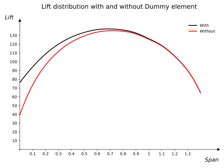
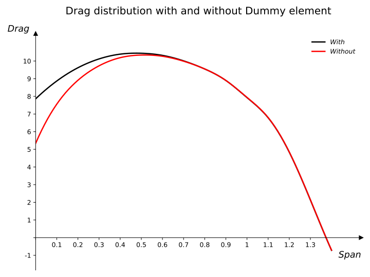
Below is the resulting lift and drag distribution for the Shaft of the Oceanis 51 at a helm angle of 8°, shown both with and without the rudder extension DummyShaft.
Note on Configuration: When adding the dummy element to the rudder, the resulting lift and drag distributions of the Shaft are independent of whether excludeFromFM is set to true or false. This occurs because the lifting line computation will account for the DummyShaft in both scenarios.